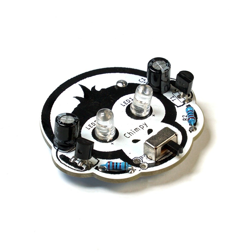
What is Chimpy….???
Welcome to the Chimpy Bistable Multivibrator (Flip-Flop Circuit) DIY Soldering Kit! This kit provides an exciting opportunity for children to learn about electronics and soldering while building a fun and interactive project.
The Chimpy PCB (Printed Circuit Board) is specially designed in the shape of a monkey or chimpanzee head, making the learning experience even more engaging. The eyes of the monkey serve as the positions for two blinking LEDs, adding a playful touch to the project.
By assembling the components on the PCB, children will gain hands-on experience with soldering techniques and learn about the functionality of electronic components. The kit includes all the necessary components, including resistors, transistors, capacitors, a switch, and a battery holder.
Once assembled, the Chimpy Bistable Multivibrator comes to life. The flip-flop circuit built on the PCB allows the LEDs to blink alternately, creating an eye-catching effect. It’s an excellent introduction to the concept of multivibrator circuits and their practical applications.
Through this DIY soldering kit, children will not only develop their soldering skills but also enhance their understanding of basic electronic principles. They’ll witness the magic of circuitry as they bring their adorable Chimpy creation to life.
The Chimpy Bistable Multivibrator DIY Soldering Kit is designed to be educational, entertaining, and safe for children. It provides a hands-on learning experience that fosters creativity, problem-solving skills, and a sense of accomplishment.
So, gather your soldering tools, put on your thinking cap, and embark on an exciting soldering adventure with the Chimpy Bistable Multivibrator DIY Soldering Kit. Let your imagination run wild as you bring the charming Chimpy to life with blinking LED eyes!

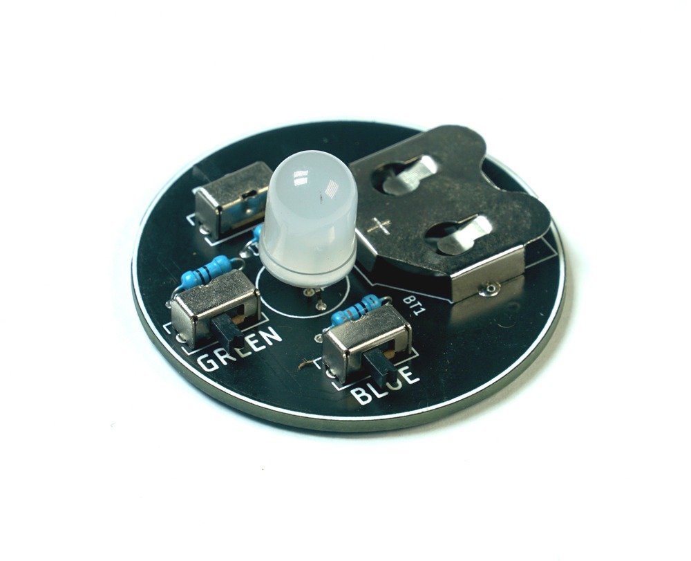
What is a Bistable Multivibrator ???
The Bistable Multivibrator is an exciting electronic circuit that adds a touch of magic to your DIY projects. Also known as a Flip-Flop circuit, it has two stable states and can remain in either state until triggered to switch.
This clever circuit is like a light switch that you can flip up or down to control the state of an LED or other electronic components. It brings reliability and versatility to various applications, from timing circuits and digital memory to control systems and sequential logic.
The Bistable Multivibrator’s simplicity lies in its ability to “remember” and hold its state until it receives a trigger signal. It can stay in one state indefinitely, making it perfect for applications where stability and control are essential.
Using components such as transistors, resistors, and capacitors, the Bistable Multivibrator offers a fascinating glimpse into the world of digital electronics. It forms the foundation for many advanced electronic devices, including computers, calculators, and even sophisticated communication systems.
With its ability to switch between states and retain information, the Bistable Multivibrator is like a digital superhero. It allows you to create circuits that store data, control processes, or provide memory functions in your projects.
So, whether you’re building a personalized blinking LED display or experimenting with electronic control systems, the Bistable Multivibrator opens up a world of possibilities. Its versatility and simplicity make it a captivating element to incorporate into your electronic creations.
Embrace the power of the Bistable Multivibrator in your DIY projects, and let your creativity and innovation shine through its flipping fun!
OK.. Let’s Start Soldering …..
-
- Step 1 : Safety First Before you begin assembling the kit, remember to follow these safety precautions:
- Work in a well-ventilated area.
- Wear safety goggles and heat-resistant gloves to protect yourself.
- Make sure your soldering iron is properly grounded and placed on a heat-resistant surface when not in use.
- Keep small components away from young children to prevent any accidents
- Step 2: Get Familiar with the Components Take a moment to identify and understand the components included in the kit. Here’s a list to help you:
- LEDs (5mm) – 2 pieces (Designators: LED1, LED2)
- Resistors (22kΩ) – 2 pieces (Designators: R1, R2)
- C828 transistors – 2 pieces (Designators: T1, T2)
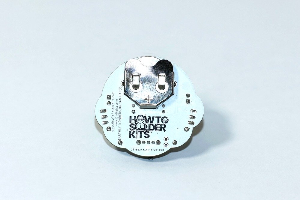
- Battery Holder MY-2032-05 – 1 piece (Designator: BT1)
- 100µF polarized capacitors – 2 pieces (Designators: C1, C2)
- Switch SK12D07VG4 – 1 piece (Designator: S1)
- Step 3: Prepare the PCB Place the Chimpy PCB in front of you with the monkey or chimpanzee head shape facing up. Take note of the markings on the PCB, such as the LED positions and component outlines.
- Step 1 : Safety First Before you begin assembling the kit, remember to follow these safety precautions:
- Step 4: Soldering the Components Follow these steps to solder the components onto the PCB:
- Start with the resistors:
-
- Identify the resistors labeled R1 and R2 on the PCB.
- Insert one 22kΩ resistor into each of the corresponding labeled spots on the PCB.
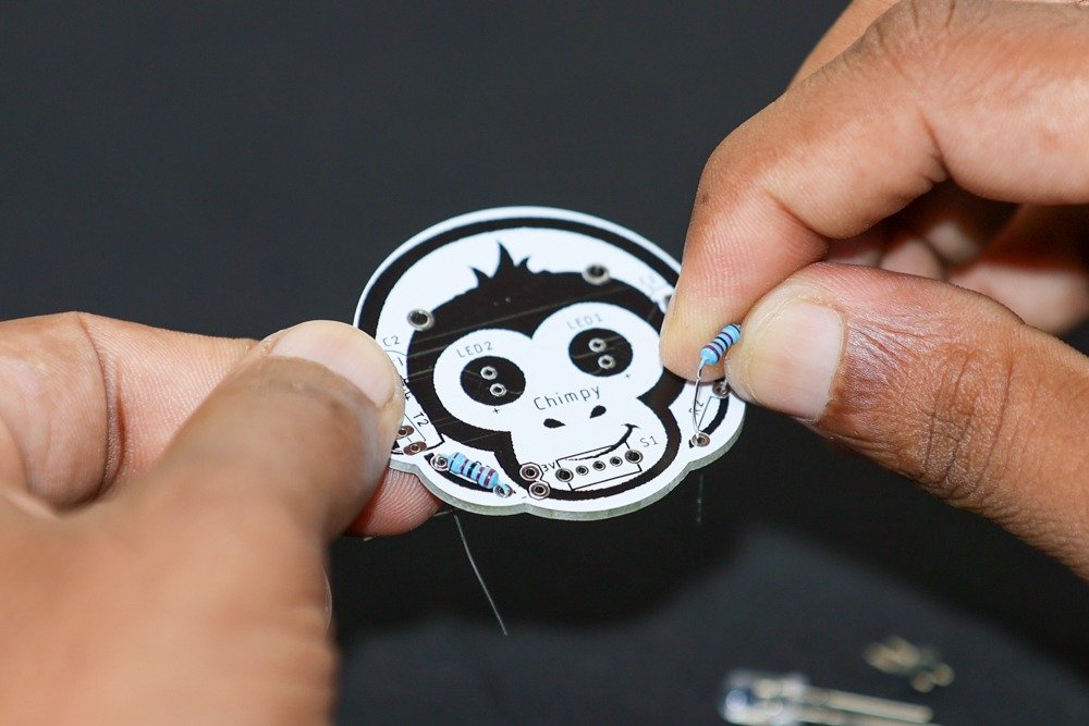
- Bend the resistor leads gently to hold them in place.
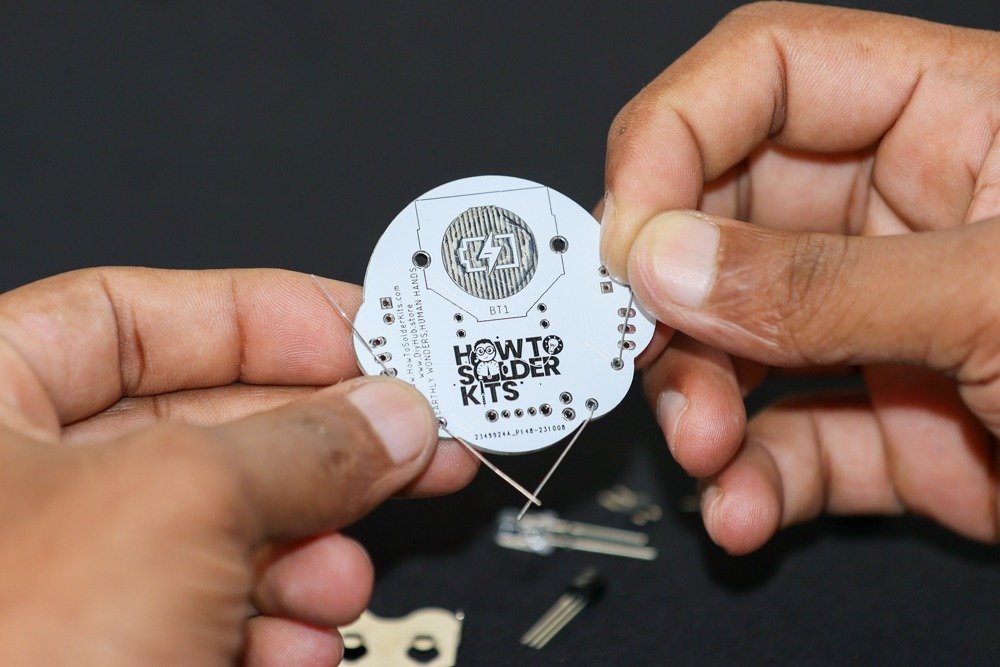
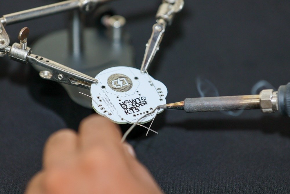
- Flip the PCB over and solder the resistor leads on the backside.
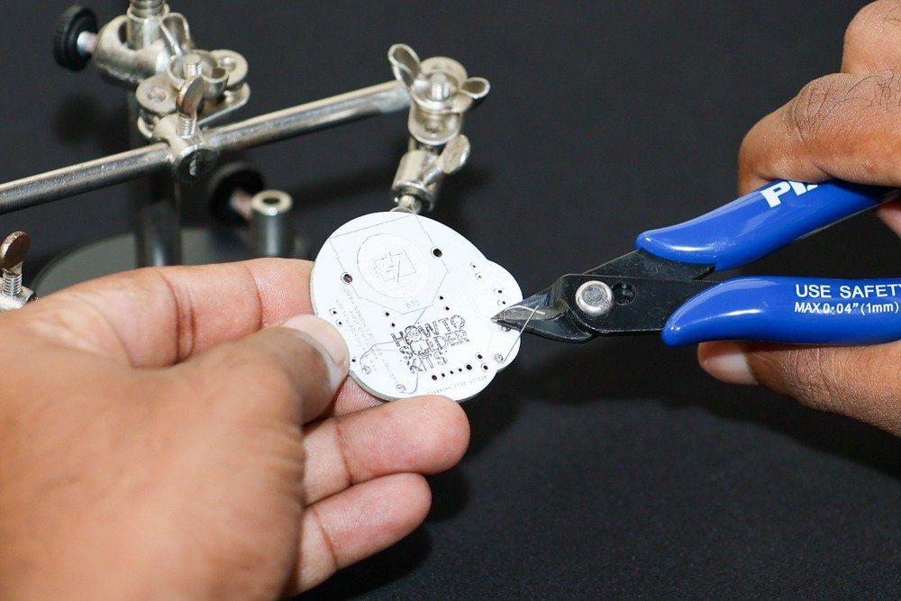
- Trim any excess leads using a wire cutter.
-
- Move on to the transistors:
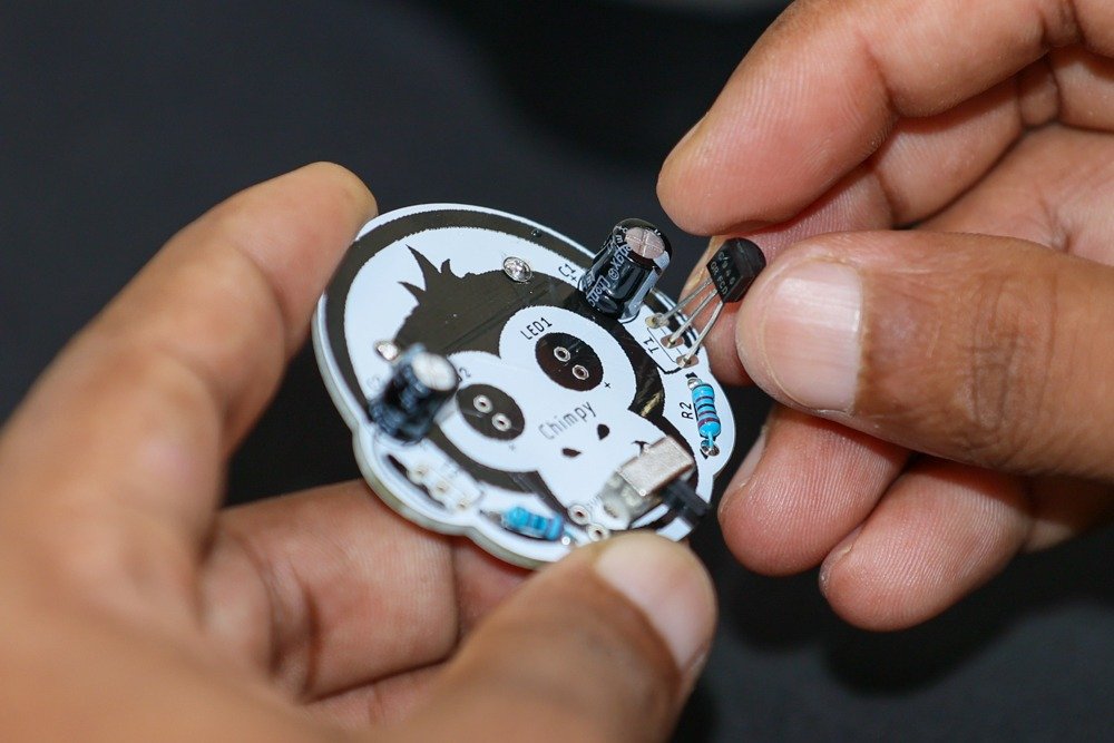
- Identify the transistor positions labeled T1 and T2 on the PCB.
- Insert one C828 transistor into each of the corresponding labeled spots on the PCB.
- Make sure the flat side of the transistors matches the flat side indicator on the PCB.
- Flip the PCB over and solder the transistor leads on the backside.
- Trim any excess leads using a wire cutter.
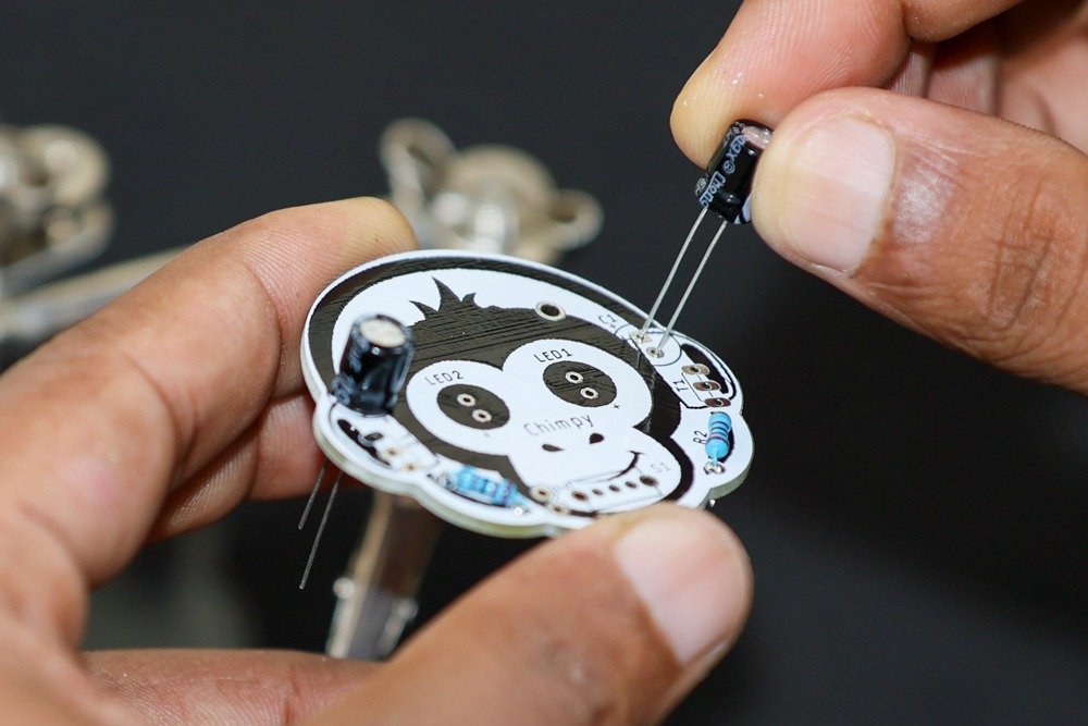
- Proceed with the capacitors:
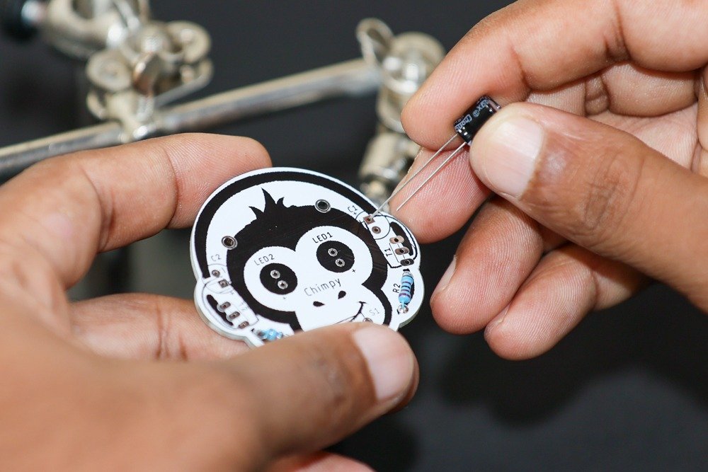
- Identify the capacitor positions labeled C1 and C2 on the PCB.
- Insert one 100µF polarized capacitor into each of the corresponding labeled spots on the PCB.
- Make sure the positive (+) and negative (-) terminals of the capacitors align with the PCB markings.
- Flip the PCB over and solder the capacitor leads on the backside.
- Trim any excess leads using a wire cutter.
- Continue with the switch and battery holder:
- Identify the switch and battery holder positions labeled S1 and BT1 on the PCB.
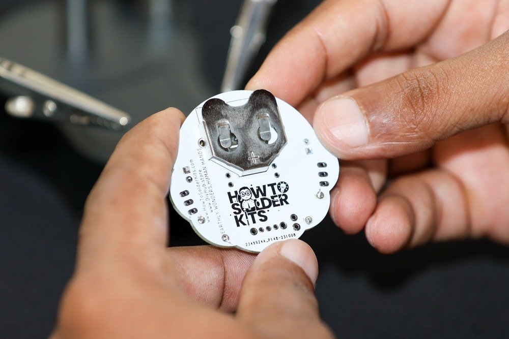
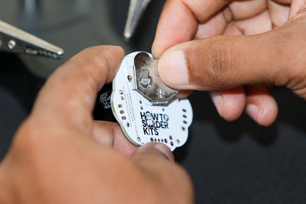
- Insert the SK12D07VG4 switch into the labeled spot for S1.
- Insert the MY-2032-05 battery holder into the labeled spot for BT1.
- Flip the PCB over and solder the leads of the switch and battery holder on the backside.
- Trim any excess leads using a wire cutter.

- Start with the resistors:
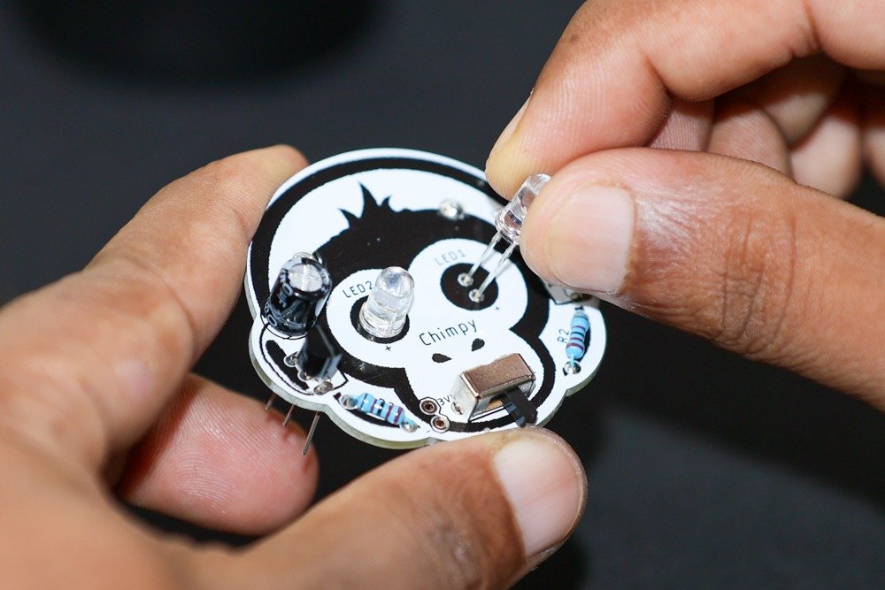
- Step 5: Soldering the LEDs
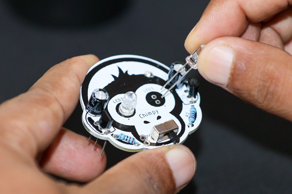
- Identify the LED positions labeled LED1 and LED2 on the PCB, which correspond to the eyes of the Chimpy shape.
- Insert one LED into each of the corresponding labeled spots on the PCB.
- Make sure the longer lead (anode) of the LED aligns with the “+” marking on the PCB.
- Flip the PCB over and solder the LED leads on the backside.
- Trim any excess leads using a wire cutter.
- Step 6: Final Checks
- Inspect the soldered connections to ensure they are solid and free from short circuits or solder bridges.
- Make sure all components are securely soldered and properly aligned with the PCB markings.
- Double-check that the polarized components (capacitors, LEDs) are inserted with the correct orientation.
- Clean the PCB with a brush or compressed air to remove any flux residue or debris.
- Step 7: Testing and Powering On
- Insert a fresh 2032 coin cell battery into the battery holder, ensuring the correct polarity.
- Slide the switch to the ON position.
- The LEDs on the Chimpy’s eyes should light up, indicating that the circuit is functioning properly.
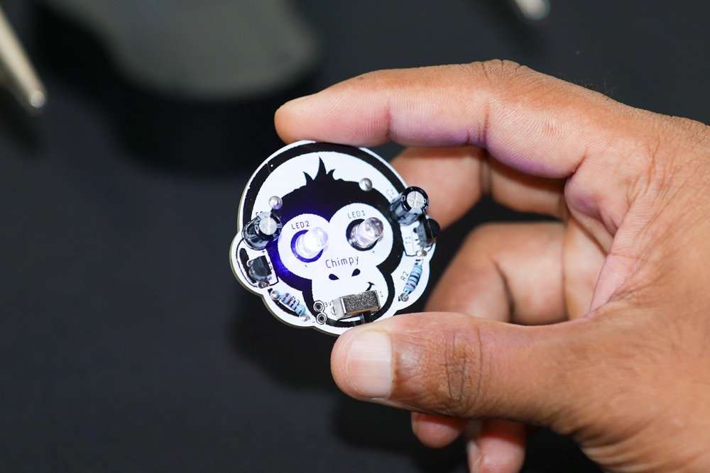
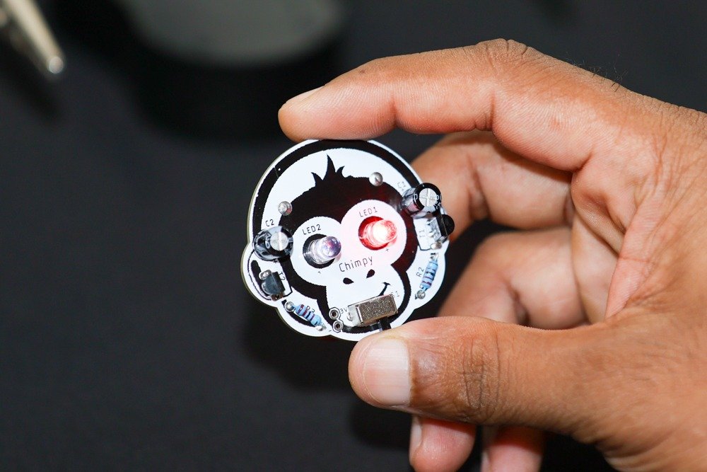
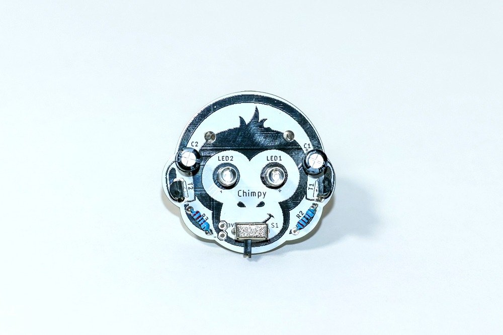
- Congratulations! You have successfully assembled the Chimpy Bistable Multivibrator (Flip-Flop Circuit) DIY soldering kit. Enjoy the playful blinking lights of your Chimpy creation!
Glossary
LED (Light-Emitting Diode):
An LED is like a magical light that uses very little energy and comes in different colors. It’s like a tiny superhero that can light up your projects without getting hot! You can find LEDs in many things like colorful signs, fancy toys, and even on the dashboard of a cool spaceship.
Resistor (Electricity Speed Bump):
A resistor is like a friendly speed bump for electricity. It helps control the flow of electricity in a circuit so that everything works just right. It’s like a superhero that keeps the electricity from going too fast or too slow, making sure all the other electronic parts play nicely together.
Transistor (Electricity On/Off Switch):
A transistor is like a tiny superhero switch for electricity. It can turn the flow of electricity on or off, just like a secret door in a super spy adventure. Transistors are the clever heroes that help make electronic devices like robots, computers, and cool gadgets come to life.
Capacitor (Quick-Charging Energy Bank):
A capacitor is like a little energy bank that can charge up really fast. It’s like a superhero that can store electrical energy and release it when needed. Capacitors are like lightning in a bottle, helping electronic devices like radios and cameras work smoothly and have enough power for fun adventures.
Slide Switch (Circuit Control Button):
A slide switch is a fantastic button that can turn your electronic creations on or off. It’s like a secret control panel that gives you the power to decide when your circuits come alive. With a simple slide, you can control lights, sounds, or even make a robot friend move!
SMD Battery (Powerful Tiny Energy Source):
An SMD battery is like a small but mighty power source for your electronic devices. It’s like a mini superhero that gives life to your toys, remote controls, and tiny gadgets. With an SMD battery, your creations can shine brightly and keep going for a long time.


