Welcome to the Breathing Heart – LED Pulse Light DIY Soldering Kit! This kit is designed to bring both educational value and a captivating visual experience. The Breathing Heart PCB is shaped like a heart, and once assembled, it will create a mesmerizing effect of LEDs pulsing in and out, simulating the rhythm of a breathing heart.
The kit includes all the necessary components to create a breathing light effect using an LM358 operational amplifier. This project provides hands-on experience with basic electronic components and soldering techniques, enhancing your understanding of how electronic circuits work.
Understanding the Breathing Heart Circuit
The Breathing Heart project features a circuit that controls 22 LEDs to create a fade-in and fade-out effect. The key component in this circuit is the LM358 operational amplifier, which is used to control the intensity of the LEDs. The pulse effect is achieved by adjusting the current flowing through the LEDs, making them gradually brighten and dim in a rhythmic pattern.
Role of the LM358 in the Breathing Heart Project
The LM358 operational amplifier (op amp) is the heart of the Breathing Heart project, playing a crucial role in creating the smooth fade-in and fade-out effect of the LEDs. Here’s what the LM358 does in this circuit:
- Signal Amplification:
- The LM358 amplifies the control signal that dictates the brightness of the LEDs.
- Pulse Width Modulation (PWM) Generation:
- The LM358 helps generate a Pulse Width Modulation (PWM) signal, which controls the brightness of the LEDs. By varying the width of the pulses, the average power delivered to the LEDs changes, making them appear to brighten and dim smoothly.
- Control of LED Brightness:
- The LM358 takes the input signal and modulates the current flowing through the LEDs, creating the breathing effect where the LEDs gradually increase in brightness and then dim down.
- Dual Op Amp Configuration:
- The LM358 contains two operational amplifiers in a single package. One op amp generates the ramp signal (sawtooth wave), and the other modulates the LED brightness based on this signal.
- Current Control:
- The LM358 ensures that the LEDs operate within their safe limits by controlling the current, preventing damage and ensuring consistent performance.
Components List:
- Resistors:
- 100Ω (R6, R7, R8, R9)
- 100kΩ (R3)
- 10kΩ (R5)
- 47kΩ (R1, R2, R4)
- Capacitor:
- 47uF (C1)
- Transistor:
- BC547 NPN (T1)
- IC:
- LM358N (IC1)
- LEDs:
- 5mm Red LEDs (LED1 to LED22)
- Potentiometer:
- 50kΩ (POT)
- Power Connector:
- External power connector (PWR)
- PCB:
- Heart-shaped PCB
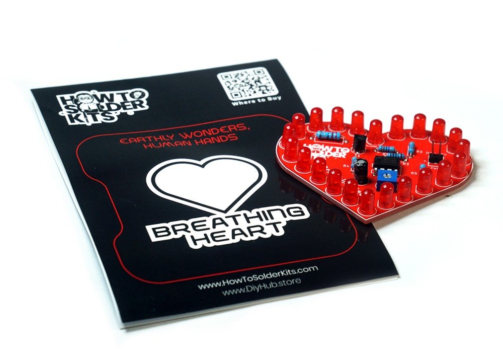
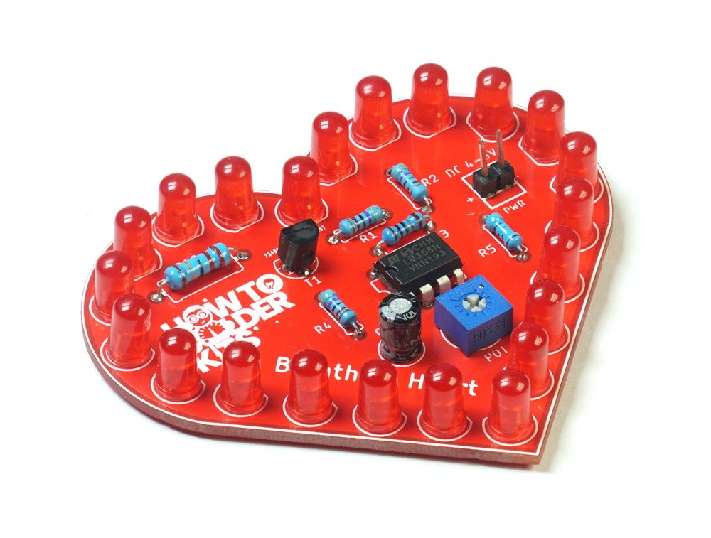
OK.. Let’s Start Soldering …..
Step 1: Safety First
Before you begin assembling the kit, remember to follow these safety precautions:
- Work in a well-ventilated area.
- Wear safety goggles and heat-resistant gloves to protect yourself.
- Ensure the soldering iron is properly grounded and placed on a heat-resistant surface when not in use.
- Keep small components away from young children to prevent any accidents.
Step 2: Identify the Components
Take a moment to identify and understand the components included in the kit. Here’s a list to help you:
- Resistors (100Ω, 100kΩ, 10kΩ, 47kΩ)
- Capacitor (47uF)
- Transistor (BC547 NPN)
- IC (LM358N)
- LEDs (5mm Red)
- Potentiometer (50kΩ)
- Power Connector
- Heart-shaped PCB
Step 3: Prepare the PCB
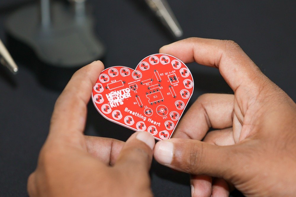
Place the Breathing Heart PCB in front of you with the top side facing up. Take note of the markings on the PCB, such as the LED positions and component outlines.
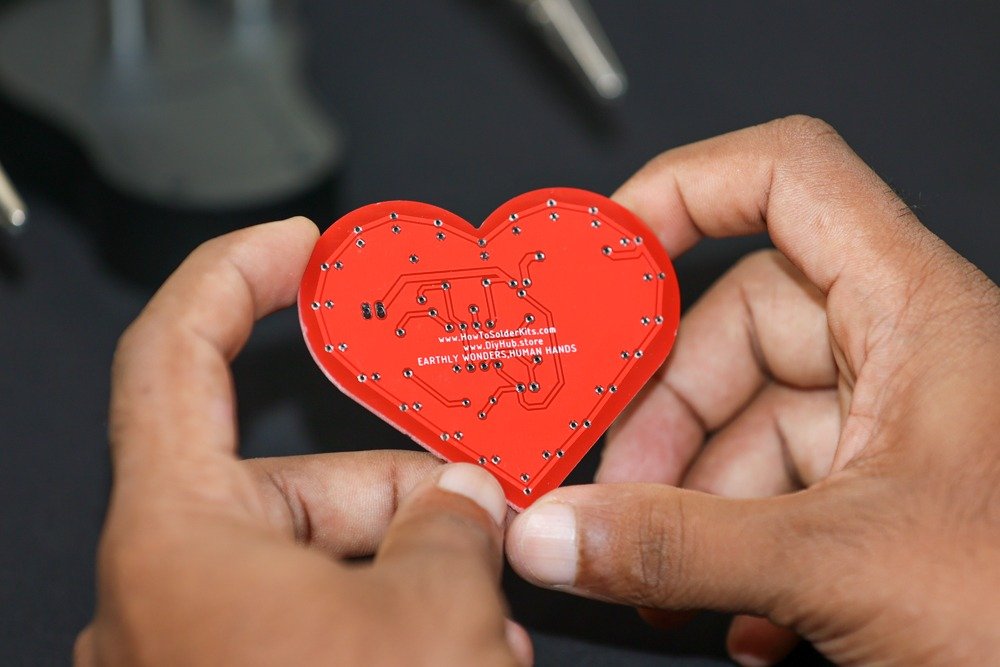
Step 4: Soldering the Components
Follow these steps to solder the components onto the PCB:
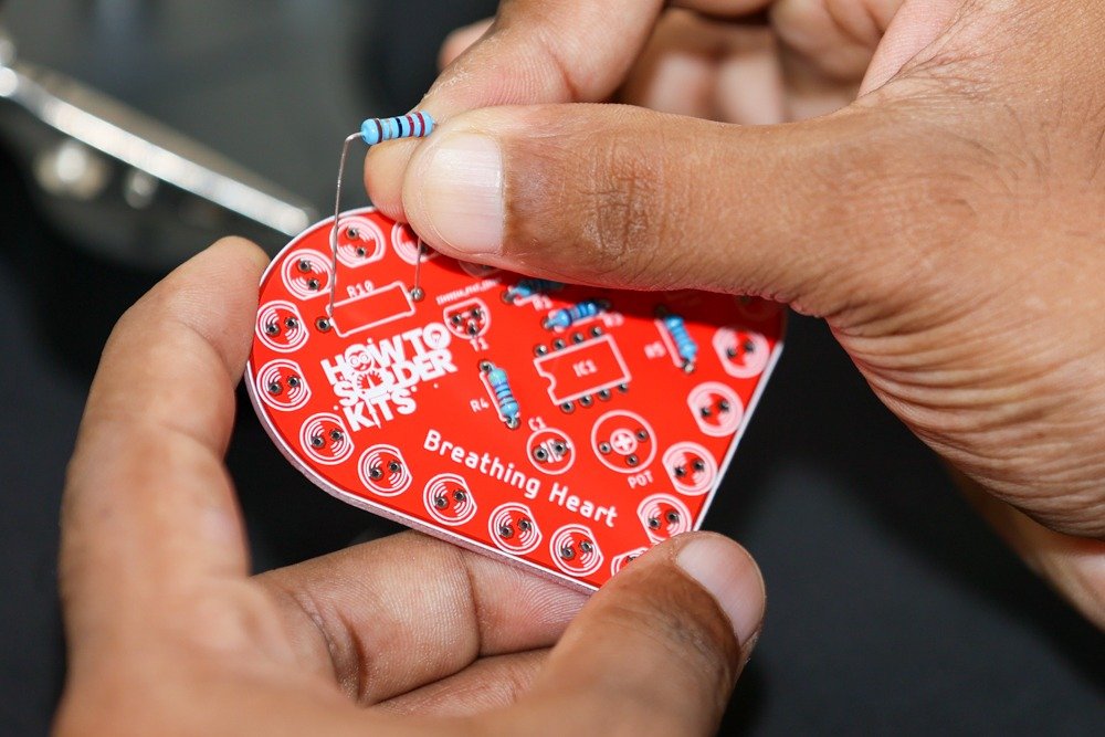
- Start with the resistors:
- Identify the resistors labeled R1, R2, R3, R4, R5, R6, R7, R8, R9, and R10 on the PCB.
-
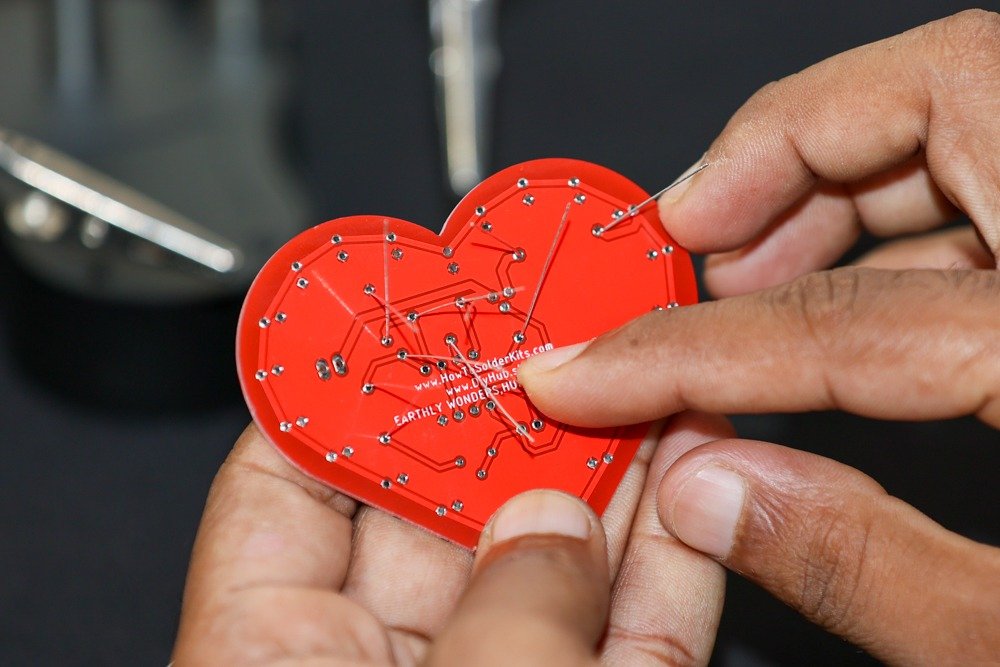
- Insert the corresponding resistors into their designated spots on the PCB.
-
- Bend the resistor leads gently to hold them in place.
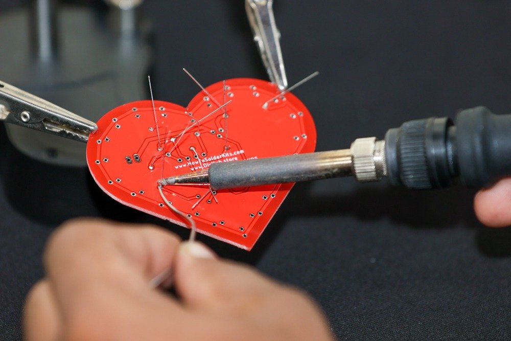
- Flip the PCB over and solder the resistor leads on the backside.
-
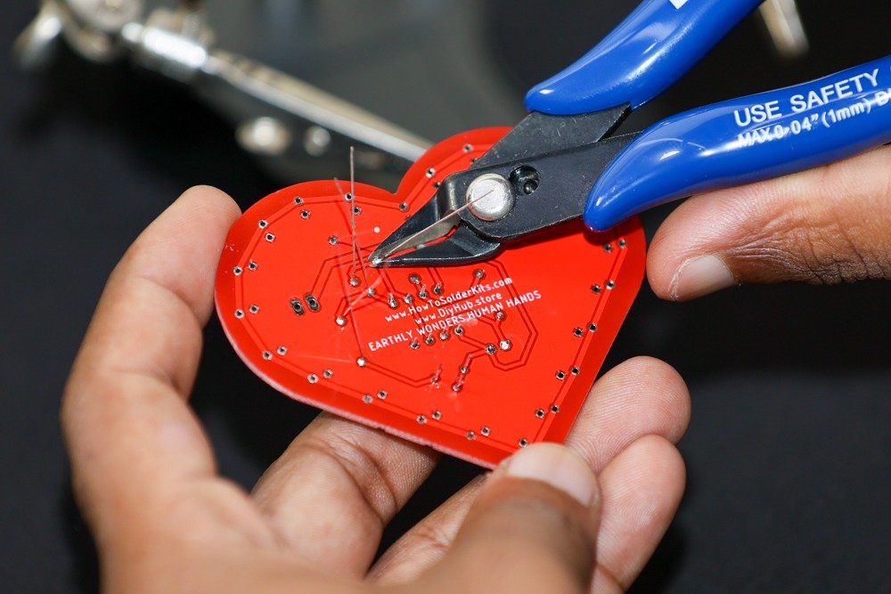
- Trim the excess leads using a wire cutter.
- Solder the capacitor:
- Identify the capacitor position labeled C1 on the PCB.
- Insert the 47uF capacitor into its designated spot, observing the polarity (longer lead is positive).
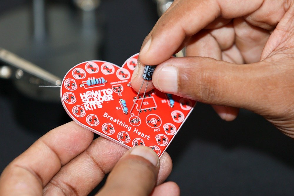
-
- Flip the PCB over and solder the capacitor leads on the backside.
- Trim the excess leads using a wire cutter.
- Solder the transistor:
- Identify the transistor position labeled T1 on the PCB.
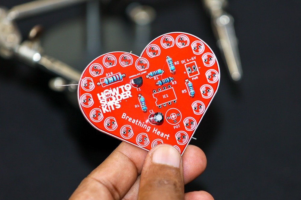
-
- Insert the BC547 NPN transistor into its designated spot, ensuring proper alignment.
- Flip the PCB over and solder the transistor leads on the backside.
- Trim the excess leads using a wire cutter.
- Solder the IC:
- Identify the IC position labeled IC1 on the PCB.
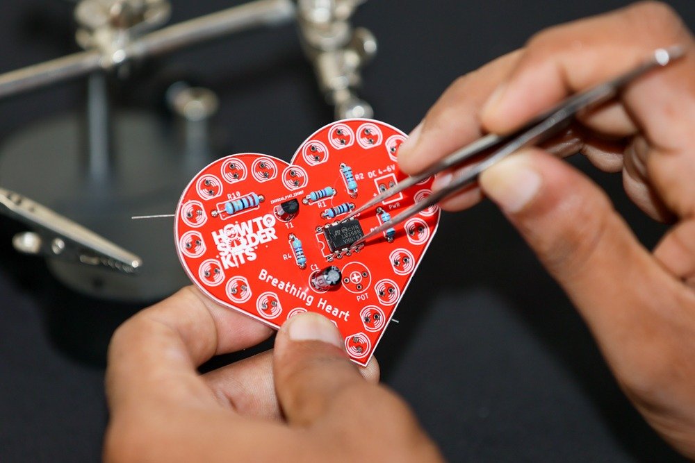
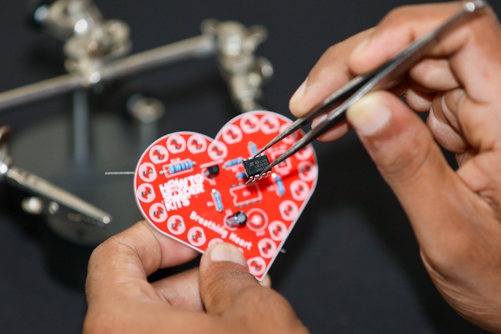
-
- Carefully insert the LM358N IC into its designated spot, aligning the notch with the marking on the PCB.
- Flip the PCB over and solder the IC leads on the backside.
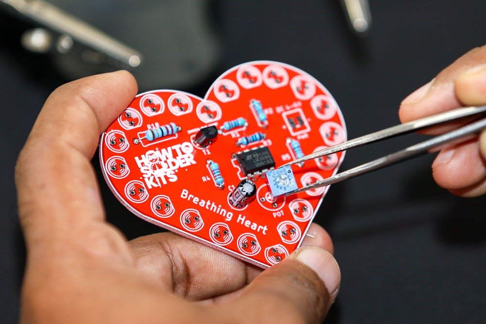
- Solder the potentiometer:
- Identify the potentiometer position labeled POT on the PCB.
- Insert the 50kΩ potentiometer into its designated spot.
-
- Flip the PCB over and solder the potentiometer leads on the backside.
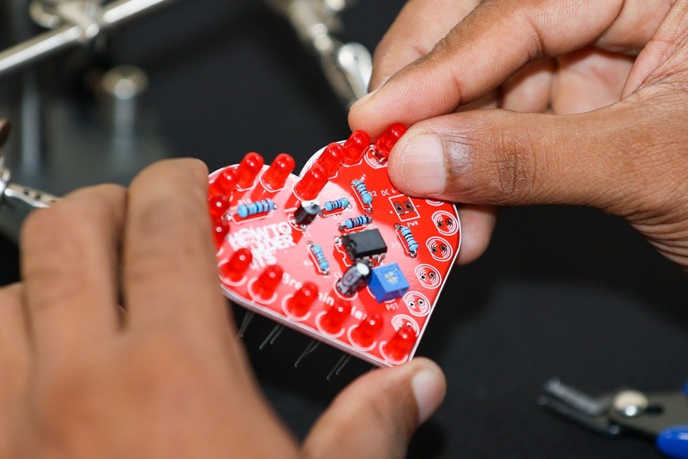
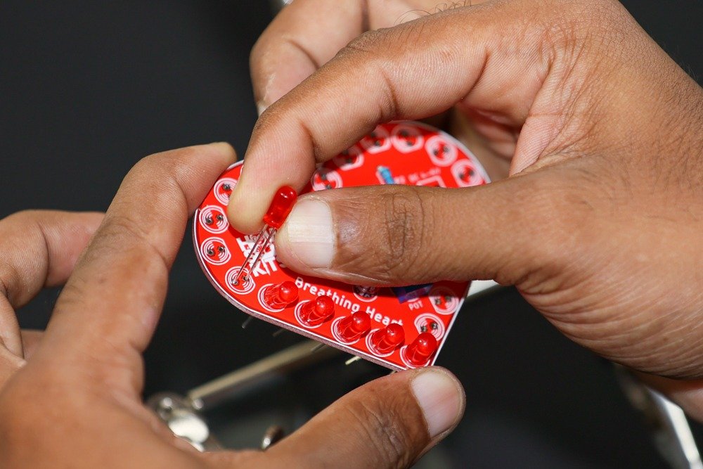
- Solder the LEDs:
- Identify the LED positions labeled LED1 to LED22 on the PCB.
-
- Insert each 5mm red LED into the corresponding spot, observing the polarity (longer lead is positive).
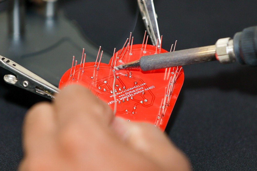
- Flip the PCB over and solder the LED leads on the backside.
-
- Trim the excess leads using a wire cutter.
- Solder the power connector:
- Identify the power connector position labeled PWR on the PCB.
- Insert the power connector into its designated spot.
- Flip the PCB over and solder the power connector leads on the backside.
Step 5: Final Checks
- Inspect the soldered connections to ensure they are solid and free from short circuits or solder bridges.
- Make sure all components are securely soldered and properly aligned with the PCB markings.
- Double-check that the polarized components (capacitor, LEDs) are inserted with the correct orientation.
- Clean the PCB with a brush or compressed air to remove any flux residue or debris.
Step 6: Testing and Powering On
- Connect an external 4-6V power supply to the PWR connector.
- Adjust the potentiometer to vary the fade-in and fade-out timing of the LEDs.
- Observe the mesmerizing effect as the LEDs pulsate and create a breathing-like motion.
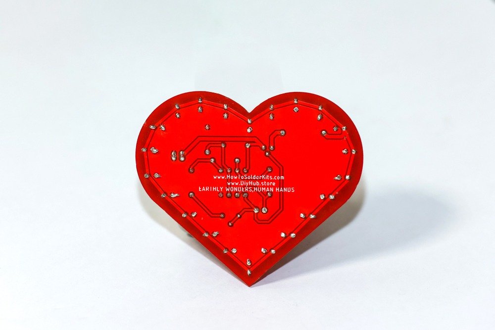
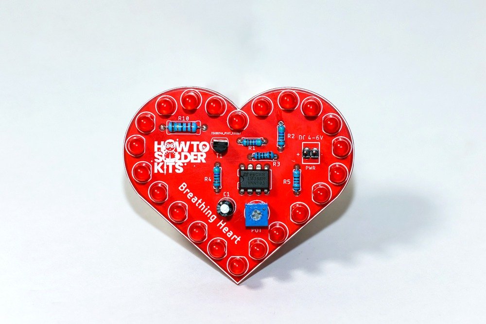
Congratulations! You have successfully assembled the Breathing Heart DIY Soldering Kit. Enjoy the captivating display of light and motion brought to life by the LM358 op amp and the synchronized pulsation of the LEDs.
Glossary
LED (Light-Emitting Diode): An LED is a special light that uses very little energy and comes in different colors. It’s like a tiny superhero that can light up your projects without getting hot! You can find LEDs in many things like colorful signs, fancy toys, and even on the dashboard of cool spaceships.
Resistor (Electricity Speed Bump): A resistor is like a speed bump for electricity. It helps control the flow of electricity in a circuit so that everything works just right. It’s like a superhero that keeps the electricity from going too fast or too slow, making sure all the other electronic parts play nicely together.
Transistor (Electricity Switch): A transistor is like an electricity switch. It’s a tiny device that can control the flow of electricity in a circuit. It acts like a gate, allowing or blocking the flow of electricity. Transistors are used in many electronic devices like computers, phones, and even toys! They help make sure electronic devices work correctly.
Capacitor (Electricity Storage): A capacitor is like a tiny battery that can store electrical energy. It can charge up and release energy quickly. It’s made up of two metal plates with a space between them. When you connect it to a power source, it stores energy, and when you disconnect it, it releases that energy. Capacitors are used in many electronic devices like radios and computers to help them work properly.
IC (Integrated Circuit): An IC, or integrated circuit, is a tiny chip that contains many electronic components like transistors, resistors, and capacitors. It can perform various functions in a circuit, such as amplifying signals, processing data, or controlling other components.
Potentiometer (Variable Resistor): A potentiometer is a type of resistor that allows you to adjust the resistance by turning a knob. It’s used to control things like volume, brightness, or in this case, the timing of the LED pulses.
PCB (Printed Circuit Board): A PCB is like a flat board that holds all the electronic parts together. It has lines made of copper that connect the different components so they can work together.
Feel free to ask if you need any additional information or further assistance!

