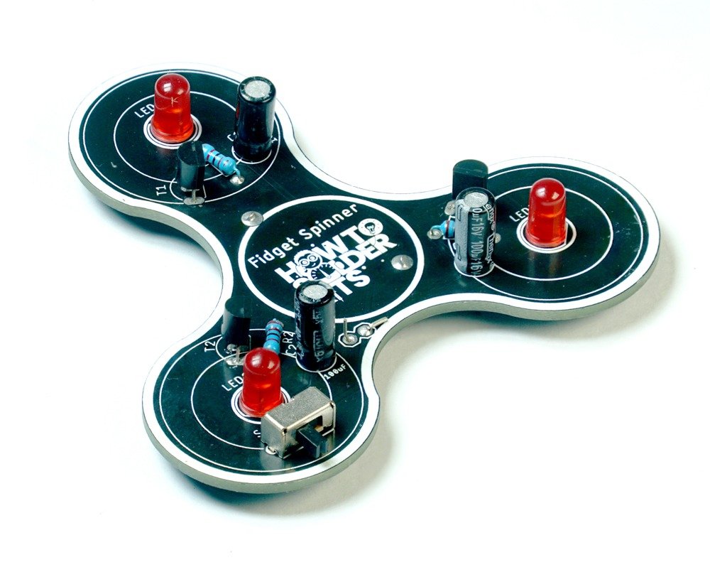
Welcome to the Fridget Spinner DIY Soldering Kit! This kit offers a fun and educational experience, allowing children to learn about electronics and soldering while creating a mesmerizing light display. The Fridget Spinner PCB is uniquely designed in the shape of a spinner, making the assembly process both engaging and enjoyable.
With this kit, you’ll assemble a three-LED astable multivibrator circuit. Once completed, the Fridget Spinner will feature three blinking LEDs, creating a captivating and colorful light show. The battery holder is conveniently located on the bottom of the PCB, providing a clean and neat appearance.
By working on this project, children will gain hands-on experience with basic electronic components and soldering techniques. The kit includes all the necessary parts: resistors, transistors, capacitors, a switch, and a battery holder. Assembling the Fridget Spinner not only enhances soldering skills but also deepens the understanding of how electronic circuits work.
The Fridget Spinner DIY Soldering Kit is designed to be both educational and entertaining. It encourages creativity, problem-solving, and a sense of accomplishment as children watch their spinner come to life with blinking lights.
So, gather your soldering tools and get ready for an exciting soldering adventure with the Fridget Spinner DIY Soldering Kit. Let your imagination and creativity shine as you build and enjoy your very own Fridget Spinner!

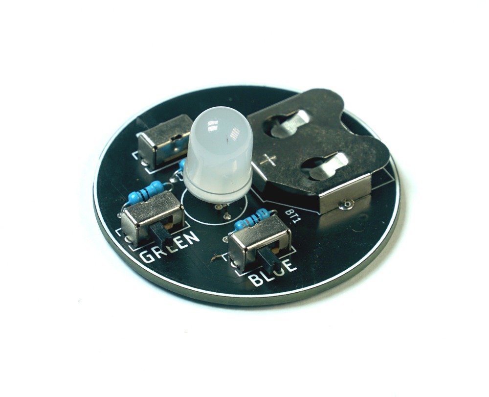
Introduction to the 3 LED Astable Multivibrator
The Fridget Spinner project features a 3 LED Astable Multivibrator circuit. An Astable Multivibrator is a type of electronic oscillator that generates a continuous, repeating output signal without needing an external trigger. It uses components such as resistors, capacitors, and transistors to create an oscillating effect.
In this project, the Astable Multivibrator drives three LEDs, making them blink in a sequence. This circuit uses the charging and discharging of capacitors to control the timing of the LED blinks. The result is a captivating pattern of blinking lights that is both fun to watch and educational to understand.
The 3 LED Astable Multivibrator in the Fridget Spinner kit introduces the concepts of electronic timing and oscillation. It’s a perfect project for young learners to explore the basics of electronics while creating a visually appealing and interactive toy.
By building and experimenting with the Fridget Spinner, children will see firsthand how electronic components work together to create dynamic effects. This hands-on experience helps demystify electronics and fosters a deeper interest in STEM (Science, Technology, Engineering, and Mathematics) fields.
Enjoy your journey into the world of electronics with the Fridget Spinner DIY Soldering Kit and discover the magic of the Astable Multivibrator circuit!
OK.. Let’s Start Soldering …..
Step 1: Safety First
Before you begin assembling the kit, remember to follow these safety precautions:
- Work in a well-ventilated area.
- Wear safety goggles and heat-resistant gloves to protect yourself.
- Ensure the soldering iron is properly grounded and placed on a heat-resistant surface when not in use.
- Keep small components away from young children to prevent any accidents.
Step 2: Identify the Components
Take a moment to identify and understand the components included in the kit. Here’s a list to help you:
- LEDs (5mm) – 3 pieces (Designators: LED1, LED2, LED3)
- Resistors (22kΩ) – 3 pieces (Designators: R1, R2, R3)
- C828 transistors – 3 pieces (Designators: T1, T2, T3)
- Battery Holder MY-2032-05 – 1 piece (Designator: BT1)
- 100µF polarized capacitors – 3 pieces (Designators: C1, C2, C3)
- Switch SK12D07VG4 – 1 piece (Designator: S1)
Step 3: Prepare the PCB


Place the Fridget Spinner PCB in front of you with the spinner shape facing up. Take note of the markings on the PCB, such as the LED positions and component outlines.
Step 4: Soldering the Components
Follow these steps to solder the components onto the PCB:
- Start with the resistors:
- Identify the resistors labeled R1, R2, and R3 on the PCB.
- Insert one 22kΩ resistor into each of the corresponding labeled spots on the PCB.
- Bend the resistor leads gently to hold them in place.
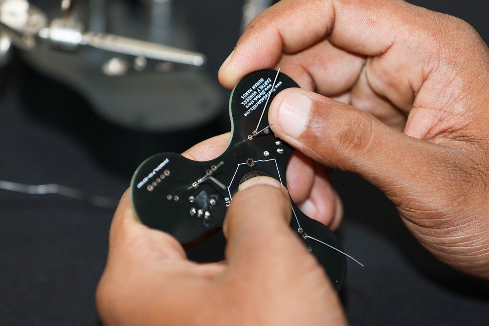
- Flip the PCB over and solder the resistor leads on the backside.
- Trim the excess leads using a wire cutter.

- Move on to the transistors:
- Identify the transistor positions labeled T1, T2, and T3 on the PCB.
- Insert one C828 transistor into each of the corresponding labeled spots on the PCB.
- Ensure the flat side of the transistors matches the flat side indicator on the PCB.
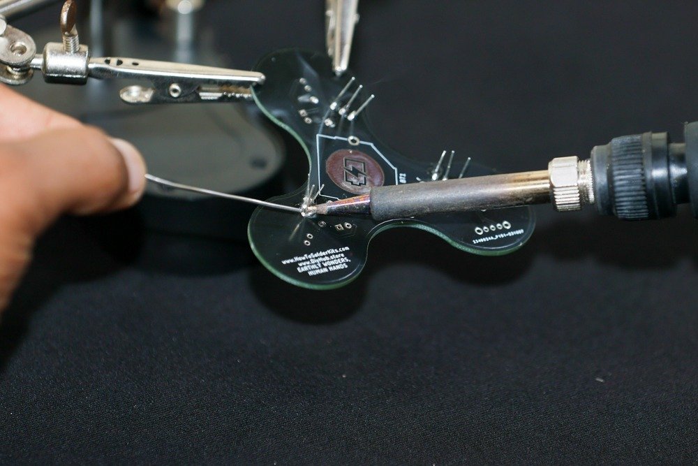
- Flip the PCB over and solder the transistor leads on the backside.
- Trim the excess leads using a wire cutter.


- Continue with the capacitors:
- Identify the capacitor positions labeled C1, C2, and C3 on the PCB.
- Insert one 100µF polarized capacitor into each of the corresponding labeled spots on the PCB.
- Ensure the positive (+) and negative (-) terminals of the capacitors align with the PCB markings.
- Flip the PCB over and solder the capacitor leads on the backside.
- Trim the excess leads using a wire cutter.
- Proceed with the switch and battery holder:
- Identify the switch and battery holder positions labeled S1 and BT1 on the PCB.
- Insert the SK12D07VG4 switch into the labeled spot for S1.
- Insert the MY-2032-05 battery holder into the labeled spot for BT1.
- Flip the PCB over and solder the leads of the switch and battery holder on the backside.
- Trim the excess leads using a wire cutter.


- Finish with the LEDs:
- Identify the LED positions labeled LED1, LED2, and LED3 on the PCB.
- Insert one 5mm LED into each of the corresponding labeled spots on the PCB.
- Ensure the longer lead of each LED (the positive lead) aligns with the “+” marking on the PCB.
- Flip the PCB over and solder the LED leads on the backside.
- Trim the excess leads using a wire cutter.


Step 5: Final Checks
- Inspect the soldered connections to ensure they are solid and free from short circuits or solder bridges.
- Make sure all components are securely soldered and properly aligned with the PCB markings.
- Double-check that the polarized components (capacitors, LEDs) are inserted with the correct orientation.
- Clean the PCB with a brush or compressed air to remove any flux residue or debris.
Step 6: Testing and Powering On
- Insert a fresh 2032 coin cell battery into the battery holder, ensuring the correct polarity.
- Slide the switch to the ON position.
- The LEDs on the Fridget Spinner should start blinking in a sequence, indicating that the circuit is functioning properly.
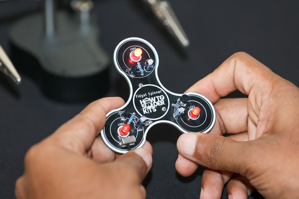

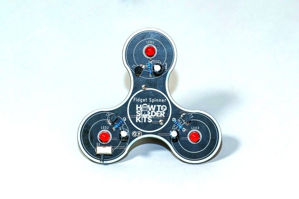
Congratulations! You have successfully assembled the Fridget Spinner DIY Soldering Kit. Enjoy the captivating blinking lights of your spinner creation!
Glossary
LED (Light-Emitting Diode): An LED is a special light that uses very little energy and comes in different colors. It’s like a tiny superhero that can light up your projects without getting hot! You can find LEDs in many things like colorful signs, fancy toys, and even on the dashboard of cool spaceships.
Resistor (Electricity Speed Bump): A resistor is like a speed bump for electricity. It helps control the flow of electricity in a circuit so that everything works just right. It’s like a superhero that keeps the electricity from going too fast or too slow, making sure all the other electronic parts play nicely together.
Transistor (Electricity Switch): A transistor is like an electricity switch. It’s a tiny device that can control the flow of electricity in a circuit. It acts like a gate, allowing or blocking the flow of electricity. Transistors are used in many electronic devices like computers, phones, and even toys! They help make sure electronic devices work correctly.
Capacitor (Electricity Storage): A capacitor is like a tiny battery that can store electrical energy. It can charge up and release energy quickly. It’s made up of two metal plates with a space between them. When you connect it to a power source, it stores energy, and when you disconnect it, it releases that energy. Capacitors are used in many electronic devices like radios and computers to help them work properly.
Switch (Electricity Controller): A switch is a device that controls the flow of electricity in a circuit. It’s like a gate that can be opened or closed to allow or block the flow of electricity. It can turn a circuit on or off. Switches are used in toys, electronic devices, and even in our homes to control lights or fans.
Battery: A battery is like a small power source that stores electricity and can be used to make things work. It comes in different sizes and can be rechargeable or disposable.
Printed Circuit Board (PCB): A PCB is like a flat board that holds all the electronic parts together. It has lines made of copper that connect the different components so they can work together.
Soldering: Soldering is like using a special metal glue called solder to join electronic parts together. It makes a strong connection between the parts and the PCB, so everything works properly.
Flux: Flux is like a special cleaner that is used when soldering. It helps remove dirt and helps the solder stick to the parts better.
Wire Cutter: A wire cutter is a tool with sharp blades that can cut wires and leads. It helps make clean cuts and trims excess parts after soldering.
Heat-Shrink Tubing: Heat-shrink tubing is a special kind of plastic tube that shrinks when heat is applied. It’s like a cover that can protect and insulate wires and connections.
Heat Gun: A heat gun is a tool that blows hot air. It can be used to shrink the heat-shrink tubing, remove old solder, or heat things during soldering or repairs.
Multimeter: A multimeter is a handy tool that can measure things like electricity and resistance. It helps test and troubleshoot electronic circuits and make sure everything is working correctly.
Feel free to ask if you need any additional information or further assistance!


