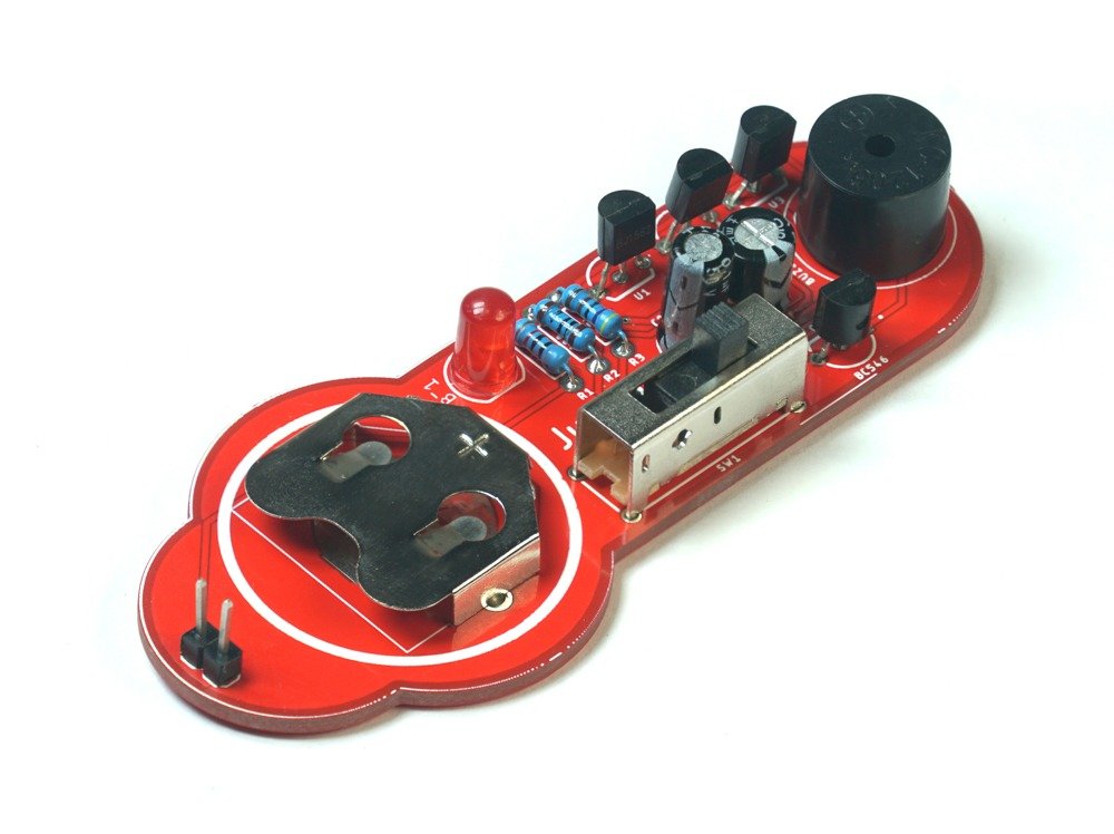
What is The JukeBox….???
Get ready to embark on a musical adventure with The JukeBox – Selectable Melody Generator DIY Soldering Kit! This exciting project allows you to build your very own selectable melody generator, bringing the joy of music right to your fingertips.
The JukeBox kit features three variations of the popular UM66 melody generator chip: UM66T08L, UM66T19L, and UM66T32L. Each chip is programmed to play a distinct melody, adding variety and charm to your musical experience. The melodies included are “Happy Birthday,” “For Alice,” and the delightful “Coo Coo Waltz.”
Choosing your desired melody with The JukeBox is a breeze. The kit is equipped with a three-way selector switch, enabling you to effortlessly toggle between the available tunes. Once you’ve made your selection, the onboard buzzer will emit the enchanting sound of your chosen melody, filling the air with musical delight.
Building The JukeBox is not only a creative endeavor but also an educational one. By following the provided instructions and assembling the components on the included PCB, you’ll gain hands-on experience with soldering techniques and learn about the inner workings of melody generators. The kit provides all the necessary electronic components, including the UM66 chips, the selector switch, the buzzer, and other required parts.
The possibilities with The JukeBox are endless. Use it to create a personalized musical greeting card, add sound effects to your DIY projects, or simply enjoy the melodies as they fill the room with joy. The JukeBox – Selectable Melody Generator DIY Soldering Kit combines the excitement of music with the satisfaction of building, making it a perfect choice for music enthusiasts, hobbyists, and anyone curious about the world of electronics.
So, get ready to immerse yourself in the world of melodies and discover the magic of music with The JukeBox – Selectable Melody Generator DIY Soldering Kit. Unleash your creativity, explore the realm of melody generators, and experience the pure delight of creating your very own musical jukebox!

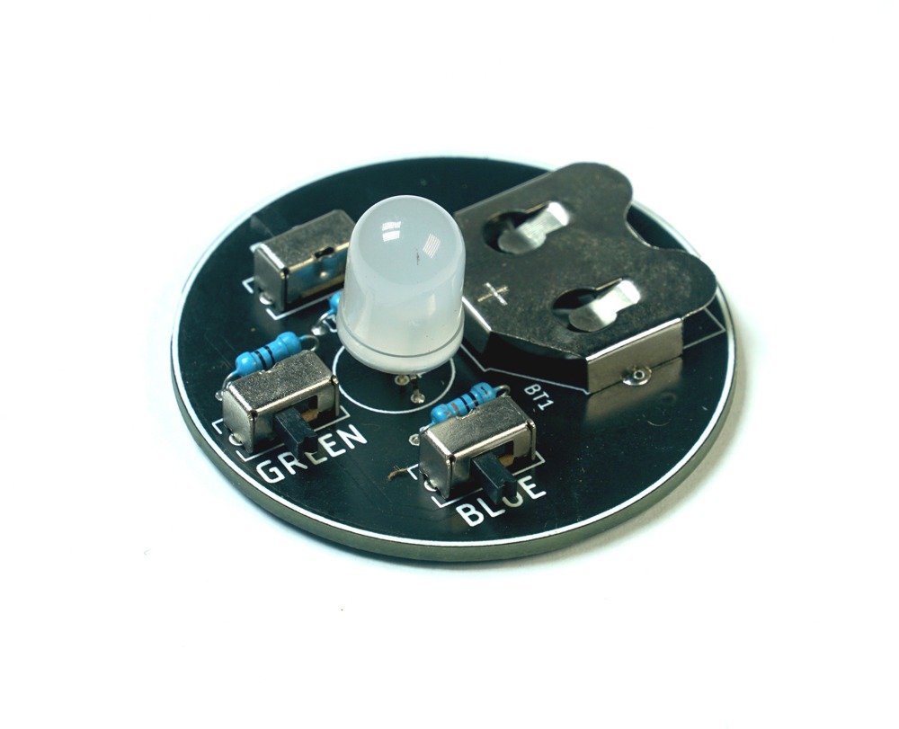
The Melodic Magic of UM66 Melody Generator ICs
The UM66 is a popular integrated circuit (IC) used for generating melodies and musical tones. It is specifically designed for small-scale applications where simplicity and ease of use are important. The IC comes in a compact package, making it ideal for use in various electronic projects and devices.
The UM66 operates on a relatively low voltage supply, typically around 3 volts, which makes it suitable for battery-powered applications. It incorporates an internal oscillator and a ROM (Read-Only Memory) that stores the musical notes and melodies. The ROM contains pre-programmed data for specific melodies, eliminating the need for external programming.
One of the key advantages of the UM66 is its simplicity of operation. It requires minimal external components, making it straightforward to integrate into a circuit. The output of the IC is designed to drive a small speaker or a piezo buzzer directly, producing the desired musical tones.
In The JukeBox DIY Soldering Kit, the UM66 melody generator ICs provide the heart and soul of the selectable melody generator. Each UM66 variant, such as UM66T08L, UM66T19L, and UM66T32L, is programmed with a different melody, allowing users to choose their preferred tune using the selector switch. When a specific melody is selected, the corresponding UM66 IC generates the musical notes, which are then played through the onboard buzzer.
The UM66 melody generator ICs offer a convenient and cost-effective solution for creating musical effects and melodies in a variety of electronic projects. Their simplicity, compact size, and pre-programmed melodies make them popular choices for hobbyists, DIY enthusiasts, and electronic musicians alike.
With the UM66 melody generator ICs at the core of The JukeBox project, you can explore the world of melodies, experiment with different tunes, and bring the joy of music to your creations.
OK.. Let’s Start Soldering …..
Step 1: Safety Precautions
Before starting the assembly, make sure to follow these safety precautions:
- Work in a well-ventilated area.
- Use appropriate safety equipment, such as safety goggles and heat-resistant gloves.
- Ensure the soldering iron is properly grounded and placed on a heat-resistant surface when not in use.
- Keep small components away from young children to avoid swallowing hazards.
Step 2: Identify the Components
Take a moment to familiarize yourself with the components included in the kit. Identify each component based on the provided parts list.
Step 3: PCB Preparation
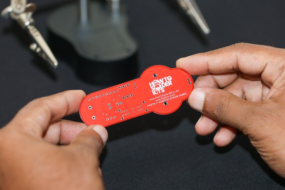
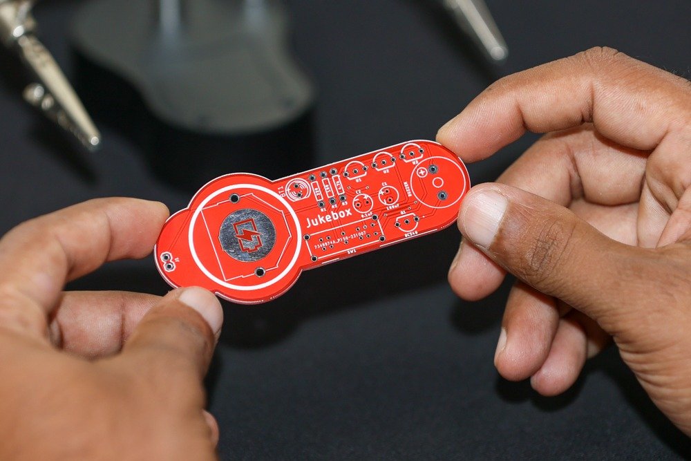
Place The JukeBox PCB in front of you. Take note of the markings on the PCB, such as the LED positions and component outlines.
Step 4: Soldering the Components
- Resistors:
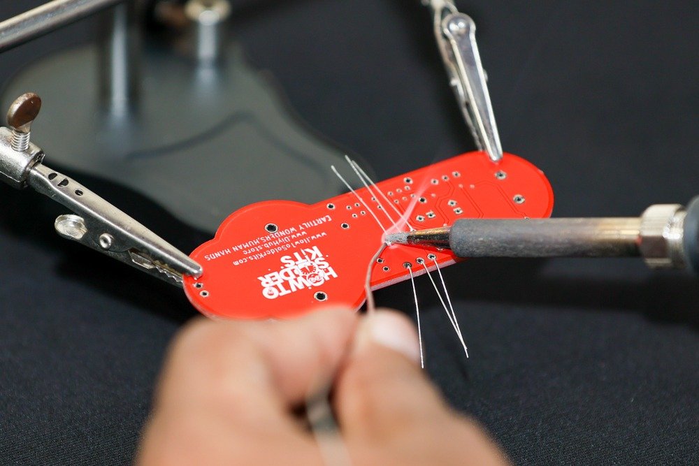
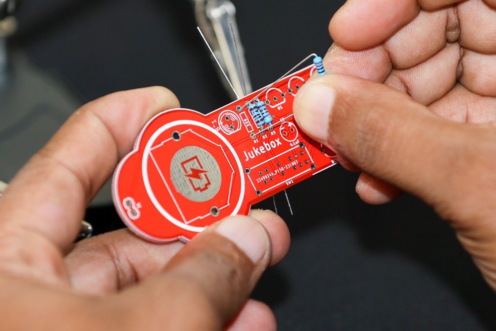
- Insert and solder the 100 Ohms resistor (R2), 220 Ohms resistor (R1), and 4.7k Ohms resistor (R3) into their respective positions on the PCB.
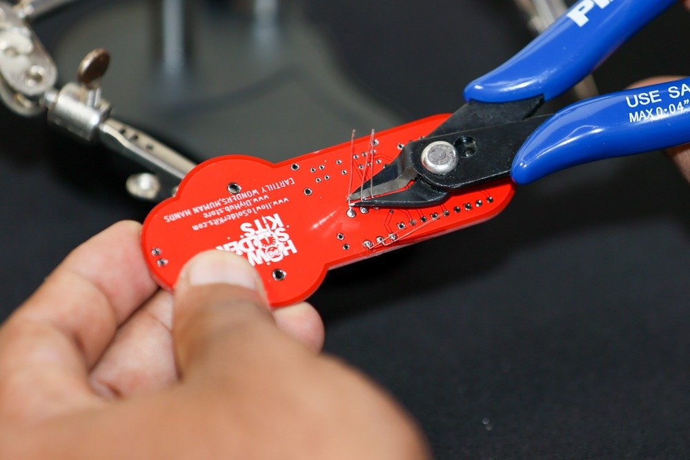
- Trim the excess leads using a wire cutter.
- Capacitors:
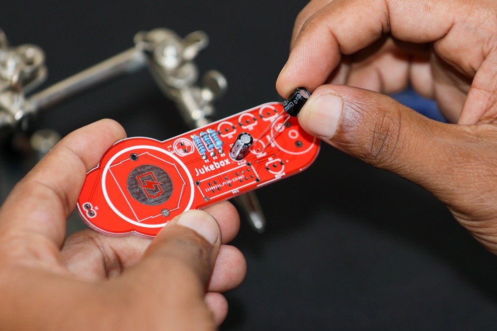
- Insert and solder the 0.1µF electrolytic capacitor (C2) and the 100µF electrolytic capacitor (C1) into their designated positions, ensuring correct polarity.
- Trim the excess leads.
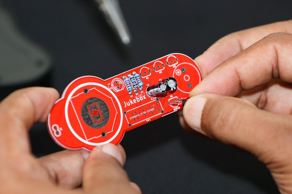
- Transistor:
- Insert and solder the BC546B NPN transistor (Q1) into its designated position. Ensure the flat side matches the PCB outline.
- Trim the excess leads.
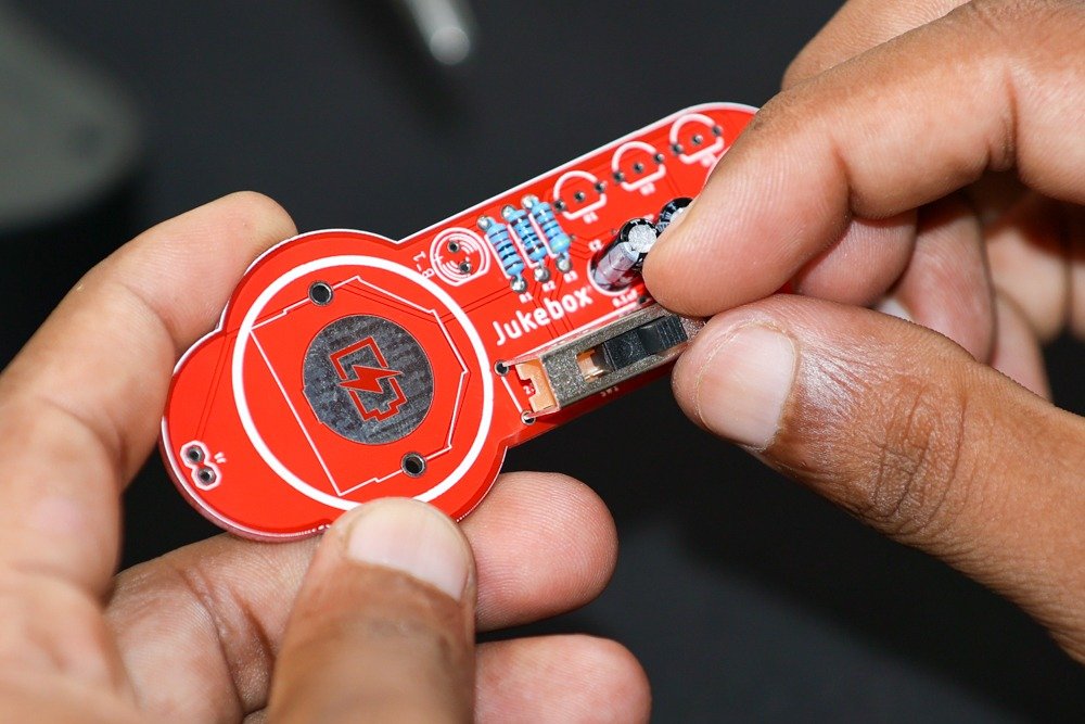
- Selector Switch and Battery Holder:
- Insert and solder the selector switch (SW1) and the CR2032 SMD battery holder (BT1) into their respective positions on the PCB.
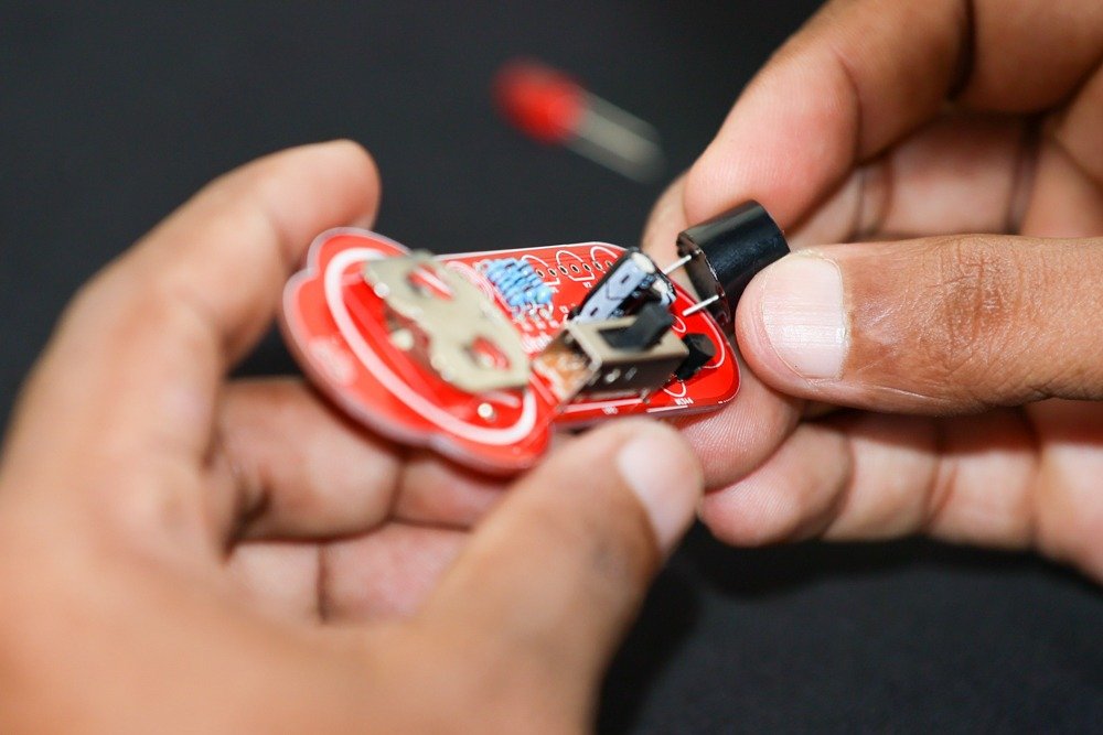
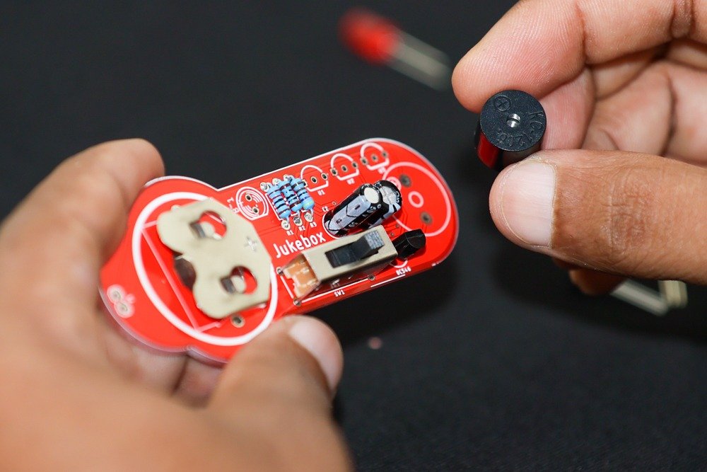
- Buzzer:
- Insert and solder the magnetic buzzer (BUZZER) into its designated position.
- LED:
- Insert and solder the 5mm LED (LED1) into its position, ensuring the longer lead (anode) is aligned with the “+” marking on the PCB.
- Trim the excess leads.

- UM66 Melody Generator ICs:
- Insert and solder the UM66T08L (U1), UM66T19L (U2), and UM66T32L (U3) ICs into their respective positions.
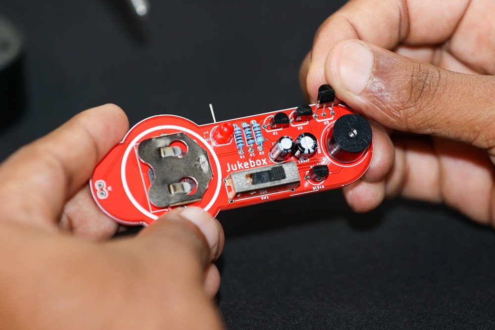
- 2-PIN Male Header:
- Insert and solder the 2-PIN male header (J1) into its designated position.
Step 5: Final Checks
- Inspect the soldered connections to ensure they are solid and free from short circuits or solder bridges.
- Make sure all components are securely soldered and properly aligned with the PCB markings.
- Clean the PCB with a brush or compressed air to remove any flux residue or debris.
Step 6: Testing and Powering On
- Insert a CR2032 battery into the battery holder (BT1) with the correct polarity.
- Set the selector switch (SW1) to the desired melody position.
- The onboard buzzer should emit the corresponding melody: “Happy Birthday,” “For Alice,” or “Coo Coo Waltz.”
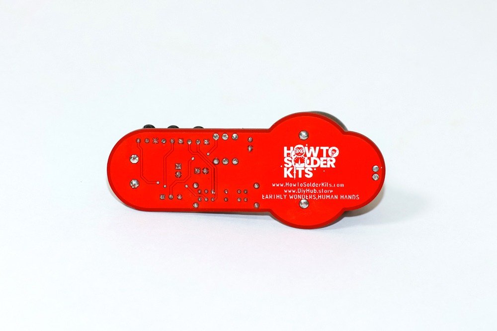
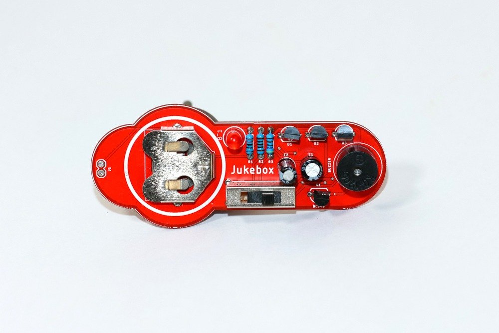
Congratulations! You have successfully assembled The JukeBox – Selectable Melody Generator DIY Soldering Kit. Enjoy creating and listening to your musical masterpiece!
Glossary
LED (Light-Emitting Diode): A semiconductor device that emits light when an electric current passes through it. LEDs are used for indication and lighting.
Resistor: A passive electronic component that limits the flow of electric current in a circuit. It helps control voltage and current levels.
Capacitor: An electronic component that stores and releases electrical energy. Capacitors are used for filtering, timing, and energy storage.
Transistor: A semiconductor device used to amplify or switch electronic signals. The BC546B is an NPN bipolar junction transistor.
UM66 Melody Generator IC: An integrated circuit that generates musical tones. Each UM66 IC is programmed with a specific melody.
Selector Switch: A switch that allows the user to select between different options, such as different melodies in this kit.
Buzzer: A component that produces sound when an electric current passes through it. The magnetic buzzer in this kit emits the selected melody.
Battery Holder: A component that holds the battery securely in place and provides electrical connections.
Header: A type of connector with pins that allows for easy connection to other components or boards.
By following this guide, you’ll not only build a fun and interactive project but also gain valuable insights into the world of electronics and soldering. Enjoy your journey with The JukeBox!


